![]()
![]()
|
|
|
Combining these features for speaker tone driven load monitoring is a feasible idea. This allows verification from the input of the pilot tone through any head end gear and wire, through the amplifier, through the speaker wires to the load.
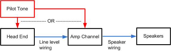
A pilot tone is used to provide a constant stimulus for both load monitoring and STS. This allows load monitoring even without program material.
The solution involves some work creating STS functionality in NWare for deployment to an nControl. This involves reading the output VU information from the amplifier and creating STS threshold and hysteresis fields. An alert is then generated when the output VU meter level falls below the STS threshold.
No changes to RTLM are needed. However, some effort is required to properly configure it to avoid false alerts. The averaged impedance measured by RTLM is influenced by the program material due to the loads impedance plot. With this plot, we can better set the upper and lower RTLM limits.
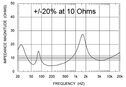
The plot shows a vented box speaker impedance. The gray area (safe operating area) shows a +/-20% margin centered about 10 Ohms. As you can see, this area does not cover a large portion of the curve. It would be wise to increase the RTLM upper and lower limits to allow more of the curve in the safe operating zone.
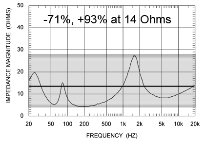
The speaker plot below has an impedance of about 14 Ohms at 19KHz. The highest impedance is 27 Ohms at 1.5KHz and the lowest impedance is about 4 Ohms at 200 Hz. So, if we set a reference impedance (train) with a 19KHz tone, we should expect to get a 14 ohm result. Since the upper and lower RTLM limits are % change thresholds, we can calculate the limits to suit the load as such.
|
Speaker impedance at 19kHz |
|
Minimum speaker impedance |
|
Maximum speaker impedance |
|
|
|
RTLM lower limit (%) |
|
|
|
RTLM upper limit (%) |
Setting the RTLM limits to these values will ensure that all measured impedances measured are in the safe operating area (gray area in graph above). If needed, the upper limit can be refined and lowered thus increasing the RTLM performance.
Note: This is based on the program material not containing 4 minutes of 1.5KHz tones.
The pilot tone dissipates less than 0.2 watts in the load above.
![]()
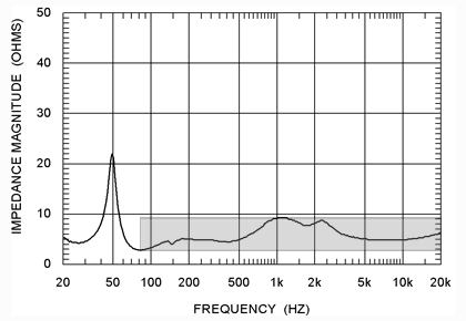
While the limit calculations above include the entire frequency (and impedance) range, the range can be narrowed to deal with frequencies contained in the program material. For instance, if the system is to be used as a paging system (voice only), the frequency range can be narrowed to deal with only the vocal fundamental frequencies. The impedance plot below shows the safe operating area of a speaker with a 4th order high-pass filter at 100 Hz. The large peak at 50 Hz can effectively be ignored, thus increasing the effectiveness of the RTLM measurement. The closer the load impedance minimum and maximum values (the smaller the safe operating area), the more effective RTLM will be.
When using RTLM without a pilot tone, the safe operating area can be narrowed even further for better RTLM performance. A typical music reinforcement system can be set up to run with a value of 20 for upper and lower limits (+/- 20% of reference impedance). Typical RTLM setup is as follows:
If training is taking more than 5 minutes, raise the pink noise level for the channel.
Besides the RTLM set up described above, the STS settings must be entered as well. As mentioned earlier, the pilot tone signal must be high enough to allow it to be detected by the output VU meter for the amplifier channel. A reading of 1.5V RMS at the output of the amplifier is sufficient. The STS software must be configured to send an alert if the output VU level falls below the user-defined threshold.
By using the suggested methods in this section, Crest CKi amplifiers can employ STS and RTLM features to ensure your system is continuously monitored from the input to the speakers.
Notes:
|
See also |