![]()
![]()
|
|
|
The NioNode Properties dialog box is displayed.
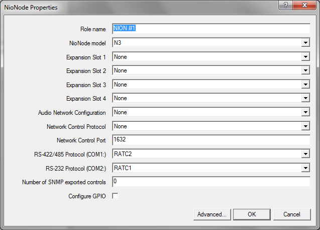
Note: The latest version of the NION NX has four expansion slots. However, older versions of the product only had two slots. If you are using an older model with two slots, you must only specify cards for slots 1 and 2.
Note: You must specify a unique role name in the Role name box. If you do not do this, an error will be displayed when you deploy the project.
Devices in your design are allocated to roles (either manually, or automatically by NWare). Roles are then assigned to MediaMatrix hardware devices for processing during deployment.
Flyoffs for each card input channel and output channel will be added to the Flyoffs tab. For information on the NION and the available cards, see http://mm.peavey.com/products/series.cfm?cat_id=54 (NION).
If you are using CobraNet, click one of the following options to specify how you want to organize the 32 input channels and 32 output channels into CobraNet network bundles.
CobraNet CM1: 4 8 Channel Bundles |
The channels are organized into four bundles of eight individual channels. |
CobraNet CM1: 8 4 Channel Bundles |
The channels are organized into eight bundles of four individual channels. |
CobraNet CM1: Advanced |
NWare allows you to specify which channels are in which bundles on a per channel basis. |
If you are using Dante network, click Dante DLM.
The default is 1632. The valid range is 1-32767.
For detailed information on the available protocols, refer to the External Control User Guide.
None/Comms processor |
Used when the project contains a Comms Processor device, or when you do not want to use the serial port. Note: If you select one of the other options – RATC2, for example, then try to use the Comms Processor device, it will not respond as quickly. |
RATC2 |
RATC2 is the improved version of RATC that was introduced with the NION platform, but is also supported by nControl and nTouch 180. Very similar to RATC1, RATC2 introduces shortened commands, and several extra functions. |
RATC1 |
RATC1 is the first generation protocol that was used in Classic frame-based MediaMatrix systems. RATC1 for NioNodes, nTouch 180 nodes and nControl nodes is equivalent to what was called RATC in Classic MediaMatrix. |
PASHA/PageMatrix |
Protocol used with the PageMatrix Command Center. It supports a four character control ID sent with the (T) trigger command. |
PASHA/XControl |
Provides basic S (Set) PASHA functionality with X‑Net2‑style trigger commands. |
PASHA/Legacy |
Designed for projects that contain legacy MediaMatrix nodes that are controlled by external programs using the classic PASHA protocol, as implemented on MainFrames and MiniFrames. When you want to replace the legacy nodes with NioNodes, select the PASHA/Legacy option and you will not need to update your external program code. This option ensures all hex values are returned from nodes in lower case instead of upper case to match the original MediaMatrix PASHA protocol. |
A flyoff for each control will be added to the Flyoffs tab. The maximum number of controls you can manage via SNMP is 512 per NioNode.
The default is 48kHz / 5.333ms.
Note: We recommend that you do not change the latency from the default setting, as it affects the timing of traffic on the CobraNet network. For more information, see Timing in the CobraNet Networking Guide.
The default is 64..65. The NioNode will automatically select a value in the specified range. If you leave this setting at the default value, a CobraNet Conductor will be selected automatically. The device with the highest value will become the Conductor, therefore selecting a higher value makes it more likely that this device will become the Conductor.
The default is 0..1. The NioNode will automatically select a value in the specified range. The NioNode with the highest value will become the XDAB master, therefore selecting a higher value makes it more likely that this NioNode will become the XDAB master.
Clock Source |
Specifies the source for the CobraNet clock signal. This is used to synchronize devices on the network. |
|
Automatic |
If a CM-1 card is fitted to the NioNode, the clock signal will be received via this interface. If no CM-1 card is fitted, the signal will be generated by the AES card. This is the default setting. |
|
CM-1 |
The clock signal will be received via the CM-1 interface. |
|
I/O slot x |
The clock signal will be received from an external source via an AES card in slot x. For information on using this setting, see Using an external clock source to synchronize devices on a CobraNet network in the NWare User Guide. |
|
The Configure NioNode GPIO dialog box is displayed.
General purpose ports 2-9,14-21 |
These ports represent the bulk of the GPIO functionality. Each of these ports can be configured as follows:
|
High current output ports 10-11,22-23 |
Each high current port provides 11.5VDC at 0.5A. High current outputs can be configured for straight logic (on/off) or PWM (Pulse Width Modulation) operation. |
Note: If you want to use the rotary encoder function, you must select rotary encoder for the pin, and the following pin must be set to unused.
For more information on the GPIO connector, see GPIO overview in the NION Hardware Manual.
|
See also Using an external clock source to synchronize devices on a CobraNet network Understanding the AES card control surface when using an external clock |