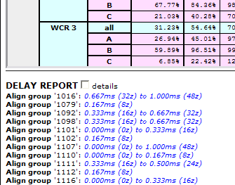
The compilation report includes a section called the delay report, which provides important information about the signal processing delays in your design.

The delays are computed by tracing the signal path from a source (typically an analog input, or possibly a signal generator) to a sink (typically an analog output, but possibly a device that combines inputs such as a mixer).
Signals pass through an A/D converter (which has a delay that is included in the computation) to a DSP; they may then be passed on one or more times to other DSPs. Each of these transfers adds to the delay. These transfers may be between DSPs on the same NioNode, or may be to another NioNode via an XDAB connection. The signal is then sent out through a D/A converter, which again adds to the delay. All these delays are totaled. All possible paths are computed, from every input to every output. The delay report identifies the maximum delay found, as well as the minimum delay. The information is shown as a period of time (in milliseconds) and number of samples (for example, 72z is 72 samples of delay).
Tips:
The report is presented in alignment groups. The most important alignment group is the analog output group. This group reports the minimum and maximum delay from any analog input to any analog output. For each combining device, such as a mixer, additional alignment groups are created. Each of these groups is identified by a device ID.
Notes:
|
See also |