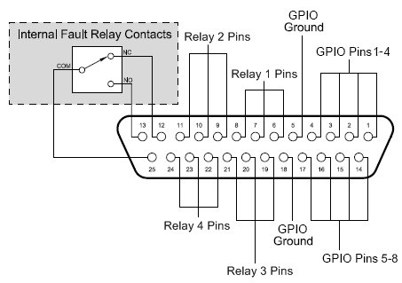
The illustration below shows the pin assignments for the CAB 4n GPIO system.

|
See also |
Pin |
Function |
Pin |
Function |
|---|---|---|---|
1 |
Configurable GPIO |
14 |
Configurable GPIO |
2 |
Configurable GPIO |
15 |
Configurable GPIO |
3 |
Configurable GPIO |
16 |
Configurable GPIO |
4 |
Configurable GPIO |
17 |
Configurable GPIO |
5 |
Ground |
18 |
Ground |
6 |
Relay 1 Common |
19 |
Relay 3 Common |
7 |
Relay 1 N.C. |
20 |
Relay 3 N.C. |
8 |
Relay 1 N.O. |
21 |
Relay 3 N.O. |
9 |
Relay 2 Common |
22 |
Relay 4 Common |
10 |
Relay 2 N.C. |
23 |
Relay 4 N.C. |
11 |
Relay 2 N.O. |
24 |
Relay 4 N.O. |
12 |
Fault Relay N.C. (1=Power off) |
25 |
Fault Relay Common |
13 |
Fault Relay N.O. (1=Power on) |
|
|
State 1 indicates continuity with pin 25.