![]()
![]()
|
|
|
The nTouch 180 Properties dialog box is displayed.
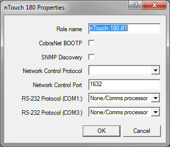
Note: You must specify a unique role name in the Role name box. If you do not do this, an error will be displayed when you deploy the project.
Notes:
Notes:
The default is 1632. The valid range is 1-32767.
Note: If you change the port number, you will have to reconfigure the clients to connect using the new port.
None/Comms processor |
Used when the project contains a Comms Processor device, or when you do not want to use the serial port. Note: If you select one of the other options – RATC2, for example, then try to use the Comms Processor device, it will not respond as quickly. |
RATC2 |
RATC2 is the improved version of RATC that was introduced with the NION platform, but is also supported by nControl and nTouch 180. Very similar to RATC1, RATC2 introduces shortened commands, and several extra functions. |
RATC1 |
RATC1 is the first generation protocol that was used in Classic frame-based MediaMatrix systems. RATC1 for NioNodes, nTouch 180 nodes and nControl nodes is equivalent to what was called RATC in Classic MediaMatrix. |
PASHA/PageMatrix |
Protocol used with the PageMatrix Command Center. It supports a four character control ID sent with the (T) trigger command. |
PASHA/XControl |
Provides basic S (Set) PASHA functionality with X‑Net2‑style trigger commands. |
PASHA/Legacy |
Designed for projects that contain legacy MediaMatrix nodes that are controlled by external programs using the classic PASHA protocol, as implemented on MainFrames and MiniFrames. When you want to replace the legacy nodes with NioNodes, select the PASHA/Legacy option and you will not need to update your external program code. This option ensures all hex values are returned from nodes in lower case instead of upper case to match the original MediaMatrix PASHA protocol. |
The Configure BootP Server dialog box is displayed.
Tip: We recommend that you leave the thread count setting set to 2.
The Configure Discovery Server dialog box is displayed.
If you want to use a broadcast address, which will provide better performance when scanning a large range of addresses, type the broadcast address.
When a large number of devices are discovered, using a broadcast address will greatly reduce the impact on the network. The format of a broadcast address is x.x.x.255. This will broadcast to the entire /24 subnet. You can also use x.x.255.255 to broadcast to a /16 subnet, but the impact of addressing such a large number of devices must be considered carefully.
Note: Not all SNMP devices will respond to a broadcast addresses. Check that the devices you are using are compatible.
If you are using a broadcast address, leave this box blank.
This feature allows devices to be detected via the switch port to which they are connected. Both the switch and the device must support SNMP. Furthermore, the device must respond to the SNMP discovery process.
|
See also |