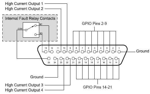
The illustration below shows the pin assignments for the GPIO system. If you are using the GPIO-25, use the screened pin numbers to identify the functions available for the associated captive wire terminal.

|
See also Configurable general purpose ports (16 control pins) |
Pin |
Function |
Pin |
Function |
|---|---|---|---|
1 |
Ground |
14 |
Configurable GPIO |
2 |
Configurable GPIO |
15 |
Configurable GPIO |
3 |
Configurable GPIO |
16 |
Configurable GPIO |
4 |
Configurable GPIO |
17 |
Configurable GPIO |
5 |
Configurable GPIO |
18 |
Configurable GPIO |
6 |
Configurable GPIO |
19 |
Configurable GPIO |
7 |
Configurable GPIO |
20 |
Configurable GPIO |
8 |
Configurable GPIO |
21 |
Configurable GPIO |
9 |
Configurable GPIO |
22 |
High current output 3 |
10 |
High current output 1 |
23 |
High current output 4 |
11 |
High current output 2 |
24 |
Ground |
12 |
Fault Relay (1=Running) |
25 |
Fault Relay Common |
13 |
Fault Relay (1=Stopped/Muted) |
|
|
State 1 indicates continuity with pin 25.