D1V front and rear panel

  1. Device selection LED Single-color green LED illuminates to indicate which of the four devices wired to the NWare D1V device is active.
  2. Knob position LED Single-color green LED array indicates current position of rotary knob.
  3. Label Space Use this area to fix a label identifying the selection that has been made. For example, the knob could switch between audio sources for background music: CD player 1 and 2.
  4. Knob Rotary encoder with integral push-switch. Turning the knob adjusts the level of the wired control. The level is indicated by lit LEDs around the knob. Pushing the knob selects a device wired to the NWare D series device.

    Note: If the LEDs start flashing, this means no NWare D series device in the NWare project has been assigned the device ID set on the physical device.
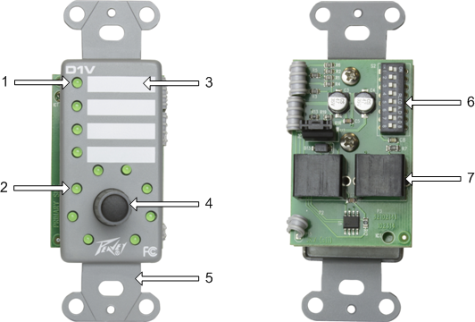
  5. Mounting Bracket Single-gang (1G) mounting bracket for installation into standard NEMA 1G switch box.
  6. DIP Switch Eight individual switches that assign button mode (switch 1), device ID (switches 3-7) and EOL termination function (switch 8). Switch 2 is reserved.
  7. RJ-45 Connectors Dual RJ-45 connectors for installation into D Series RS-485 network. These connectors are wired in parallel and include data and power supply connections. The recommended cable is UTP Category 5 (CAT5) or better.

See also

Description

Features

Applications

D4S front and rear panel